NOMINAL SLING STRENGTH
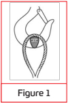
Is based upon the nominal (catalog) rope strength of the wire rope used in the sling and other factors which affect the overall strength of the sling. These other factors include splicing efficiency, num- ber of parts of rope in the sling, type of hitch (e.g. straight pull, choker hitch, basket hitch, etc.), diameter around which the body of the sling is bent (D/d) and the diameter of pin used in the eye of the sling (Figure 1).
SLING ANGLE
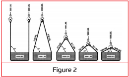
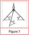
Nominal Sling Strength is the angle measured between a horizontal line and the sling leg of the body. This angle is very important and can have a dramatic effect on the rated capacity of the sling. As illustrated above, when this principle applies whether one sling is used to pull at an angle, in a basket hitch or for multi-legged bridle slings. Sling angles of less than 30 degrees are not recommended.
CHOKER HITCH
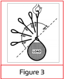
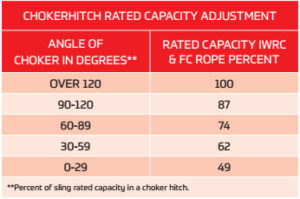
Sling Angle configurations affect the rated capacity of a sling. This is because the sling leg or body is passed around the load, through one end attachment or eye. The contact of the sling body with the end attachment or eye causes a loss of sling strength at this point. If a load is hanging free, the normal choke angle is approximately 135 degrees. When the angle is less than 135 degrees an adjustment in the sling rated capacity must be made (Figure 3). As can be seen, the decrease in rated capacity is dramatic. Choker hitches at angels greater than 135 degrees are not recommended since they are unstable.
Extreme care should be taken to determine the angle of choke as accurately as possible.
NOMINAL SPLICE EFFICIENCY
Nominal Splice Efficiency is the efficiency of the sling splice. Any time wire rope is disturbed such as in splicing an eye, the strength of the rope is reduced. This reduction must be taken into account when determining the nominal sling strength and in calculating the rated the capacity. Each type of splice has a different efficiency, thus the difference in rated capacities for different types if slings. Nominal splice efficiencies have been established after many hundreds of tests over years of testing.
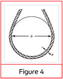
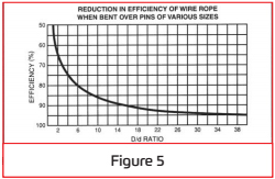
D/d ratio is the ratio of the diameter around which the sling is bent divided by the body diameter of the sling (Figure 4). This ratio has an effect on the rated capacity of the sling only when the sling is used in a basket hitch. Tests have shown that whenever wire rope is bent around a diameter the strength of the rope is decreased. Figure 5 illustrates the percentage of decrease to beexpected.
This D/d ratio is applied to wire rope slings to assure that the strength in the body of the sling is at least equal to the splice efficiency. When D/d ratios smaller than those listed in the rated capacity tables are necessary, the rated capacity of the sling must be decreased.
RATED CAPACITY
Rated Capacity is the maximum static load a sling is designed to lift. The tables give rated capacities in tons of 2000 pounds. Rated capacities contained in all the tables were calculated by computer. Each value was calculated starting with the nominal component rope strength and working up from there. Due to computer rounding of numeric values, rated capacity values for 2, 3 or 4 leg slings may not be even multiples of single leg values and may differ by a small amount. This represents the state- of-the-art technology and tables found in other publications which differ by this small amount should not be construed to be in error. The difference is generally no more than one unit for any slingdiameter.
When a wire rope is bent around any sheave or other cir- cular object, there is a loss of strength due to this bending action. As the D/d ratio becomes smaller this loss of strength becomes greater and the rope becomes less effi- cient. This curve, derived from actual test data, relates the efficiency of a rope to different D/d ratios. This curve is based on static loads only and applies to 6X19 and 6X37 class ropes.
PROOF LOAD
Proof Load is a specific load applied o a sling or assembly in a non-destructive test to verify the workman- ship of the sling. All swaged socket or poured socket assemblies should be proof loaded. The proof load is generally two (2) times the vertical rated capacity for mechanical splice slings. The maximum proof load for hand tucked slings is 1.25 times the vertical rated capacity. Care should be taken to assure that sling eyes are not damaged during the proof load.
EYE DIMENSIONS
Eye Dimensions are generally eight (8) sling body diameters wide by sixteen (16) body diameters long. Whenever possible thimbles are recommended to protect the rope in the sling eye. Eye dimensions for thimbles are contained in table 2. Table 2 contains only dimensions for thimbles used in standard single part slings. Other spe- cialized thimbles are available. Consult your sling manu- facturer for details.
PIN DIAMETER
Pin Diameter should not be any greater than the natural width of the sling eye. For any sized eye and type of sling body, the maximum allowable pin diameter may be calcu- lated as follows.
Maximum pin diameter = (2L + W) x 0.2 WhereL = length of eye W = width of eye
The minimum pin diameter should never be smaller than the nominal sling diameter.
GRADE & CONSTRUCTION
Grade & Construction of wire rope for slings is generally accepted to be bright Improved Plow Steel or Extra Improved Plow Steel grade 6×19 or 6×37 classification regular lay. IWRC rope has a higher rated capacity than Fiber Core rope for mechanically spliced slings, but the same rated capacity for hand tucked slings. This is because when making a hand tucked splice, the core (IWRC) of the rope is cut in the splice area and doesn’t add to the overall strength of the sling. Rated capacities of slings using galvanized rope depend on the method of galvanizing. The sling manufacturer should be consulted regarding rated capacities for these types of slings.
MECHANICAL SPLICE
 MECHANICAL SPLICE slings come in two basic types. One being the Returned Loop and the other the Flemish Eye or farmers splice. In either case, the splice is com- pleted by pressing (swaging) one or more metal sleeves over the rope juncture.
The returned loop is fabricated by forming a loop at the end of the rope, sliding one or more metal sleeves over the short end of the loop eye and pressing these sleeves to secure the end of the rope to the sling body. This makes an economical sling and in most cases one that will give satisfactory service. A drawback to this type of sling is that the lifting capacity of the sling depends 100% upon the integrity of the pressed or swaged joint. Should the metal sleeves(s) fail, the entire eye will also fail.
The flemish eye splice is fabricated by opening or unlaying the rope body into  two parts, one having three strands and the other having the remaining three strands and the core. The rope is unlayed far enough back to allow the loop or eye to be formed by looping one part in one direction and the Flemish eye spliceother part in the other direction and lay- ing the rope back together. The strands are rolled back around the rope body. A metal sleeve is then slipped over the ends of the splice and pressed (swaged) to secure the ends to the body of the sling. Nominal splice efficiencies expressed in table 4 and in the rated capacity tables are based on this splicing method. Splice efficiencies for other splicing methods should be confirmed by the sling manufacturer. Notice that the splice efficiency factor plays no role in the calculation of the Choker Hitch rated capacity. This is because as the rope passes through the eye of the sling in a choke, the weakest part of the sling is in the body of the sling at the choke point. Thus the splice being higher in efficiency, has no effect on the rated capacity, because the efficiency factors are not additive. Rated capacities for single part, choker and basket hitches are calculated exactly the same as for hand tucked slings except for the nominal splice efficiencies. The rated capacities adjustment table 1 for choker hitches also applies for mechanical spliced slings. Minimum D/d ratio for basket hitches is 25. This larger D/d ratio is required because the Nominal Splice Efficiency is higher.
ZINC OR RESIN POURED SOCKET TYPE TERMINATIONS
While some people may debate whether zinc or resin poured sockets are truly slings, they are generally included in the sling category. This type of termination has tradi- tionally been the method for determining the rope’s actual breaking strength. All other types of end terminations have been compared to poured sockets. Their efficiency is therefore established to be 100% for all grades and constructions ofrope.
Choker hitches are not used as much with poured sockets as which the other more general types of slings. When such slings are used in a choker hitch, the rated capacity adjustment table 1 applies.
Rope assemblies with poured attachments are generally used as a straight tension member where the rope body does not contact the load and is otherwise kept free from distortion or physical abuse. In such cases the minimum recommended design factor is 3.0. If the assembly is used as a sling then a design factor of 5.0 should be used to calculate the rated capacity. Rated capacities for these slings used in basket hitches are the same as mechanical spliced slings and use the same D/d ratiofactors.
Length tolerances or poured attachments can be somewhat more stringent than other types of slings. The manufacturer should be contacted and agreement reached before the order is placed. Tolerance as small as plus or minus 1/8” is not out of the ordinary for this type of assem- bly. Specifications such as type of fitting, pin orientation, whether zinc or resin is to be used and type of application should also be supplied to the manufacturer when ordering these types of assemblies. Those inexperienced in the socketing process should not try to fabricate assemblies without first getting expert training. It is far better to leave fabrication of this type of assembly to the experts. The fol- lowing socketing methods are general in nature and have withstood the test of time. Slight variations to these methods will produce equal results.
The two procedures, while achieving the same end result, differ significantly. It is highly recommended that all poured sockets whether they be zinc or resin, be proof loaded.
CABLE-LAID WIRE ROPE SLINGS
Cable-laid slings are fabricated from a machine made for hand tucked slings are about the same as for any other type of sling. The use of a swivel on a single leg lifts as well as free hanging loads which may rotate is not recommended. A tag line should always be used to prevent rotation of the sling body.
When the sling body of a hand tucked splice is allowed to rotate, the splice could unlay and pull out, thus causing the load to drop.
CABLE-LAID WIRE ROPE SLINGS
Eye Dimensions are generally eight (8) sling body diameters wide by sixteen (16) body diameters long. Whenever possible thimbles are recommended to protect the rope in the sling eye. Eye dimensions for thimbles are contained in table 2. Table 2 contains only dimensions for thimbles used in standard single part slings. Other spe- cialized thimbles are available. Consult your sling manu- facturer for details.
PIN DIAMETER
Pin Diameter should not be any greater than the natural width of the sling eye. For any sized eye and type of sling body, the maximum allowable pin diameter may be calcu- lated as follows.
Maximum pin diameter = (2L + W) x 0.2 WhereL = length of eye W = width of eye
The minimum pin diameter should never be smaller than the nominal sling diameter.
GRADE & CONSTRUCTION
Grade & Construction of wire rope for slings is generally accepted to be bright Improved Plow Steel or Extra Improved Plow Steel grade 6×19 or 6×37 classification regular lay. IWRC rope has a higher rated capacity than Fiber Core rope for mechanically spliced slings, but the same rated capacity for hand tucked slings. This is because when making a hand tucked splice, the core (IWRC) of the rope is cut in the splice area and doesn’t add to the overall strength of the sling. Rated capacities of slings using galvanized rope depend on the method of galvanizing. The sling manufacturer should be consulted regarding rated capacities for these types of slings.
How to Order Wire Rope
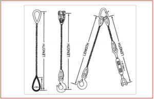
- LENGTH : The length of each piece and the number of pieces required should be specified
- DIAMETER : Specify the exact diameter of rope required.
- CONSTRUCTION : It is necessary to state the required construction of the rope.
- FINISH : When galvanized finish is required, it should be so stated. If no finish is stated, bright, or ungalvanized, finish will be furnished,
- GRADE : The grade of steel should be stated, i-e. Improved Plow Steel (IPS) or Extra-improved Plow Steel (XIP).
- PREFORMING : The requirement of preformed or non-preformed rope must be specified.
- LAY : The direction and type of lay should be specified. If no lay is specified, Right Regular Lay will be furnished.
- CORE : Specify which type core is desired.
- PURPOSE : It is desirable that you state the purpose or end use of the rope.
- Termination fittings : Eye size, thimble, socket, button etc.
Construction or Classification
- 6 x 7 class (6 strands of 7 wires)
- 6 x 19 class (6 strands of 9 – 26 wires per strand)
- 6 x 37 class (6 strands of 27 – 49 wires per strand)
- 8 x 19 class (rotation resistant)
- 19 x 7 class (rotation resistant)
- 35 X 7 class (High Performance Ropes)
- 7 x 19 construction
- 7 x 7 construction
- 1 x 19 strand
- 1 x 7 strand
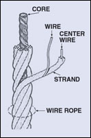
Wire Rope Core
FC (Fiber Core: manila or sisal)
IWRC (Independent Wire Rope Core)
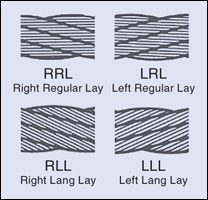
Lay Direction / Lay Type:
- RRL (Right Regular Lay)
- LRL (Left Regular Lay)
- RLL (Right Lang Lay)
- LLL (Left Lang Lay)
Grade:
- IPS (Improved Plow Steel) or 1760 N/mm2 or Grade110/120
- EIPS (Extra Improved Plow Steel) or 1960 N/mm2 or Grade 115/125
- EEIPS (Extra Extra Improved plow Steel) or 2160 N/mm2 or Grade 130/140
Finish:
- Drawn Galvanized
- Bright
- PVC Coated